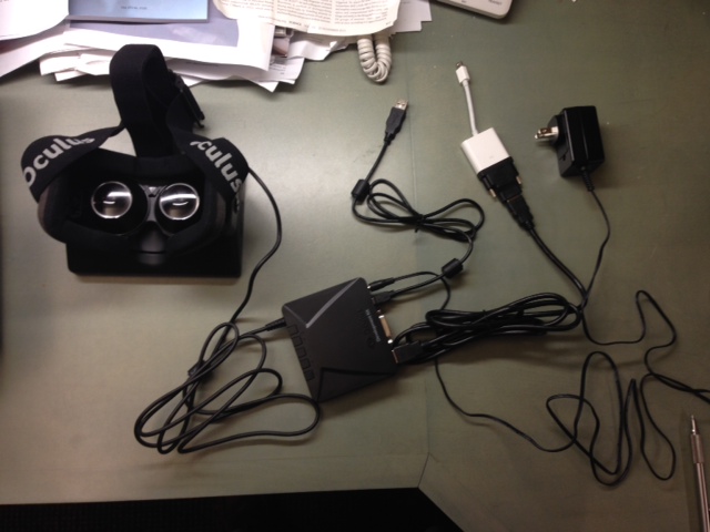
USB for head tracking,
power adapter.

Tom Goddard
March 11, 2014
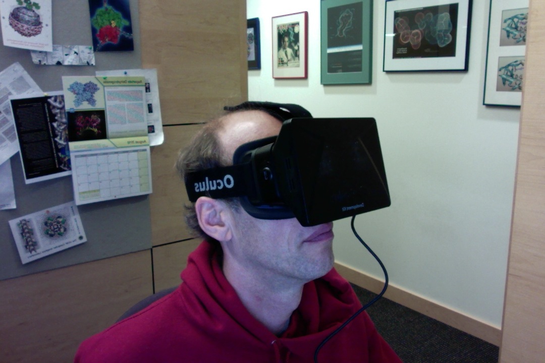
Here are notes about experiments using Oculus Rift stereo goggles with our next generation molecular visualization prototype software called Hydra. I used the developer kit 1 (DK1) Oculus Rift borrowed from Graham Johnson at UCSF. The Oculus Rift is not yet available as a consumer product expected to be released in late 2014 or early 2015.
Graham Johnson got the Oculus Rift developer kit in order to preview videos made for planetarium domes since access to an actual planetarium dome is limited. We have not tried this. Possibly VR Player can do this.
The Oculus gives a wide field of view (about 90 degrees) and stereoscopic depth, and tracks head orientation allowing you to look in all directions. Your vision is entirely filled with the virtual scene. This is significantly different from traditional stereo visualization on a desktop computer display or projector image because those technologies typically give a narrow field of view (typically 30 degrees), with no head tracking to allow viewing in other directions. The traditional methods show the molecules floating out in front of you and you cannot get to close to them because the line of sight from your eye to the molecule them misses the screen.
Despite the unique capabilities of the Oculus we have not come up with compelling applications for molecular visualization and analysis. The basic problem is that just looking at models or image data has very limited use. Researchers need to analyze the data, align models, fit molecular structures in image data, evaluate sequence conservation, setup docking or electrostatic calculations. All of this requires more user interface beyond simply looking at the data. The Oculus doesn't provide a way to interact with conventional 2-dimensional user interfaces. A large effort would be needed to create software to display user interface controls in the Oculus 3d view. The very low resolution of the display would allow only very simple interfaces with very large text. The Oculus configuration utility is an example of this. Even with a higher resolution the inability to see your keyboard, mouse, trackpad, and other applications like email or a web browser make it highly doubtful that adequate user interface to do analysis of molecular structures would be possible.
So the most plausible use is to show others features of 3-dimensional data sets from an immersive viewpoint, for example, as demonstrations to students, or showing research collaborators findings obtained with more conventional computer analysis. The device generates lots of excitement about both the technology and the scientific data being viewed, and this inspirational role may justify using the device.
|
|
|
|
|
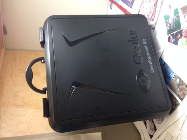
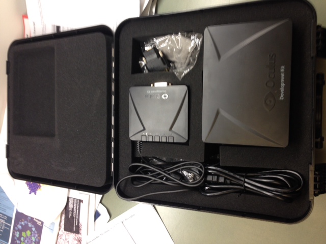
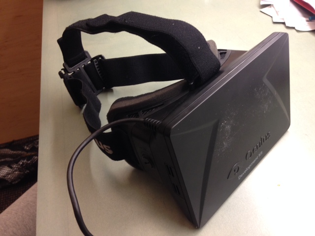
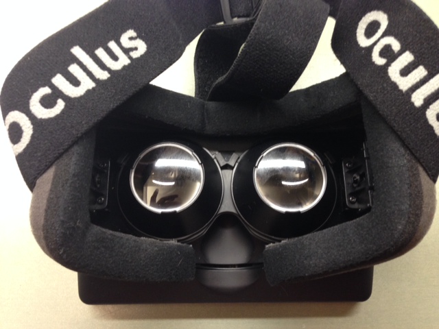
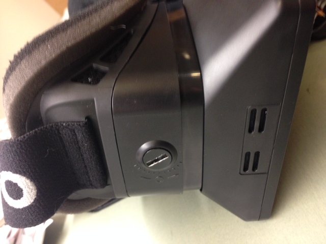
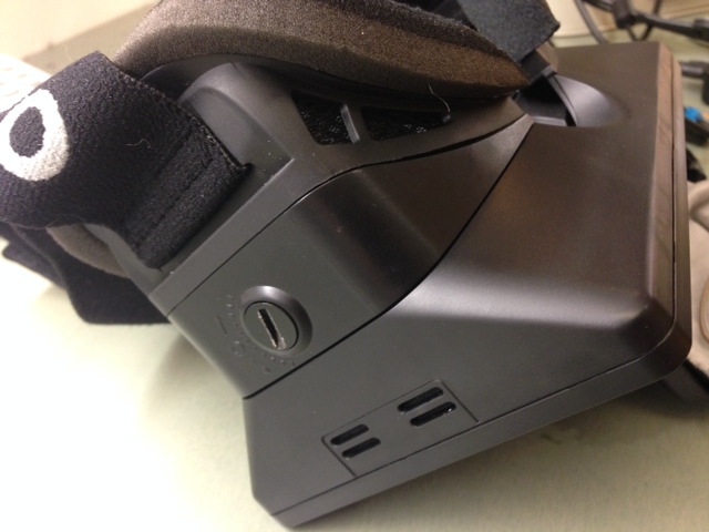
| Carrying case. | HDMI for video, USB for head tracking, power adapter. | Goggles are light. | |
|
|
|
|
|
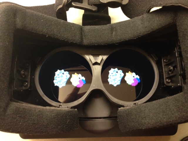
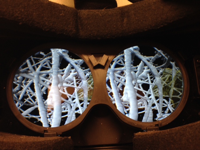
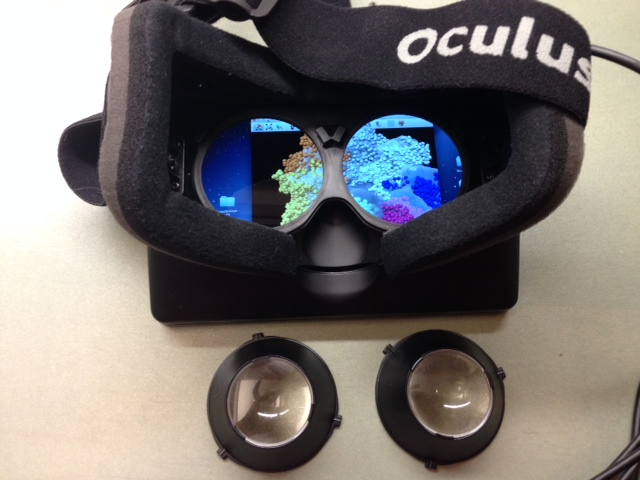
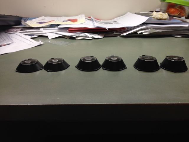
| Lenses | Lenses removed. | Collagen, lenses removed. | Photo through one lens. |
To use the Oculus I modified our Hydra visualization program to read the head orientation from the device, and display left and right eye views side by side as required. This required about 700 lines of new code (500 in Python and 200 in C++). The C++ code interfaced to the Oculus SDK library to get head tracking and a dozen device parameters (screen size, lens separation, lens distortion coefficients...). Hydra is not yet released.
There are a large number of issues that have to be dealt with in the client application. The Oculus Rift is just a flat panel display with orientation tracking hardware (magnetometer, accelerometer, and gyroscopes) in a pair of ski goggles. The Oculus SDK does the sensor fusion to compute the absolute orientation (using the magnetic field direction, the downward direction of gravity, and gyroscopes for fast rotations). The Oculus SDK does not assist with rendering the graphics, except to provide the many parameter values needed.
I tried adding minimal Oculus support and gradually learned why every suggested rendering detail was important to get good visual quality.
1) Wall-eye stereo. First I tried no Oculus support at all. The device requires side by side left and right eye images, so I used the "wall-eye" stereo mode already supported in Chimera. It was tricky to find parameters (separation of the two images) that made the two images to converge. Because the molecule is the only object in the field of view, it was alarming when turning my head caused the molecule to move to wherever I looked. Since I did not use head tracking the molecule simply stayed in the same place on the Oculus display. Next I added code to Hydra to render the left and right eye images with the proper field of view side by side on the Oculus display and use the Oculus head orientation for drawing every frame.
2) Image centering. Initially I centered each eye image on the left half and right half 640 by 800 pixel regions of the Oculus screen (full screen size 1280 by 800). This does not work because the lenses are separated by less than half the screen width so the images need to be centered closer to the center of the screen using parameters read from the device. The Oculus display is 15 cm wide, with lens separation 6.35 cm, and human eye separations (called interpupillary distance) range from about 5.7 to 7.1 cm (5th to 95th percentile).
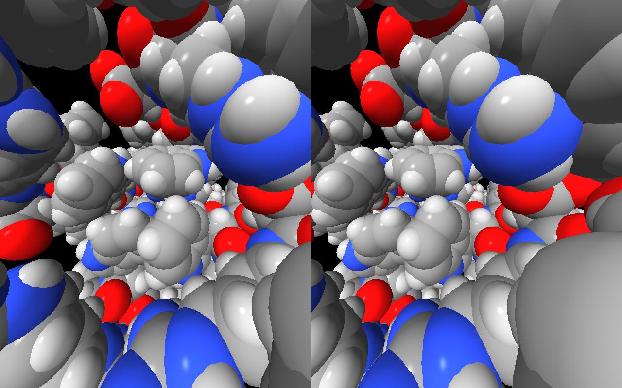
3) Lens distortion. The Oculus SDK Overview is a very clearly written 50 pages. It suggests several refinements to how the scene is rendered. The lenses introduce spherical aberration so that objects in your peripheral vision are stretched. They suggest you correct this by warping each eye image using a GPU shader program that runs on the perspective projection image to undo the spherical aberration. The warping was unpleasant and nausea inducing. Because the stretching is different for each eye both the size and depth of the molecule appears to change at the periphery. During a head turn the molecule appears no longer solid. So I added the extra GPU shader pass that uses OpenGL texture mapping to warp the image to undo the barrel distortion of the lenses.
| 
|
| Without lens distortion correction. | With distortion correction. |
4) Chromatic aberration. Different frequencies of light refract at different angles through the lenses. It takes very expensive multilayer lenses to correct this chromatic aberration, and the Oculus is a cheap $300 device does not have these, so blue and orange color fringes are visible especially on gray or white objects in the periphery of the field of view. Oculus suggests you correct this in your GPU shader by warping the red and blue color channels differently so that the lenses will then merge the colors. Looking at a gray network of collagen filaments, the colors fringes were distracting so I added this refinement. It does not work perfectly because the red, green, and blue color components of a screen pixel are not at sharp frequencies but cover a large range of frequencies. So the correction actually introduces new small fringes in the center of view. But overall it was a very noticeable improvement.
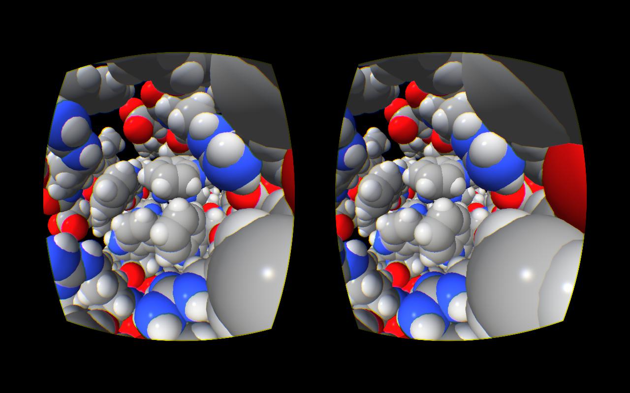
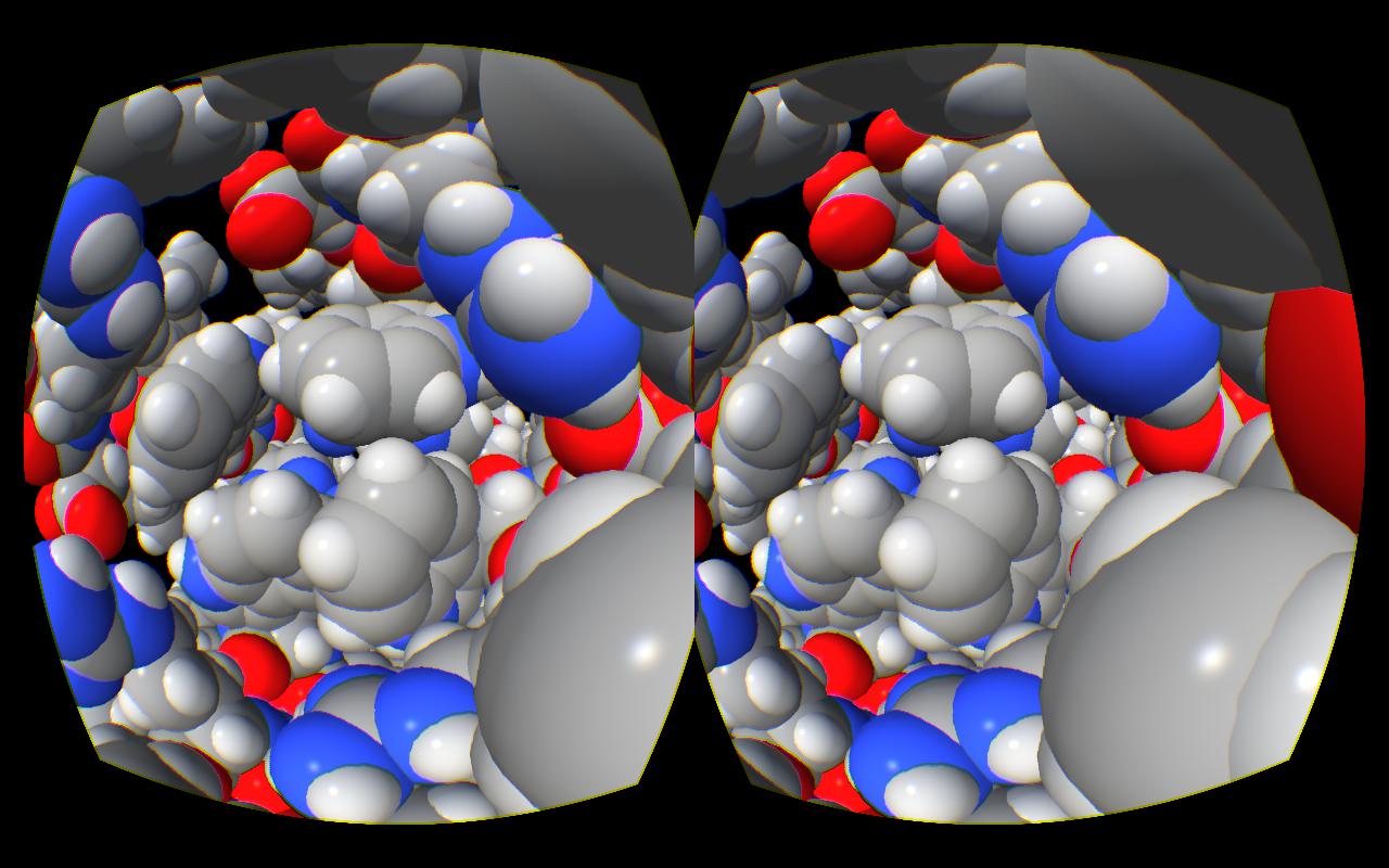
5) Image scaling. The GPU rendering correction for lens barrel distortion pulls the edges of the images towards the center. This causes the left and right eye images not to fill the screen -- only about half the screen area is used. A wider field of view can be viewed if the edges of the display are used. To achieve this we simply render the larger field of view. In order not to degrade the image quality in the center of view we have to render to a larger off-screen buffer than the actual display size. This slows the rendering. The Oculus SDK Overview recommends increasing the field of view so the left and right display edges are used, but the top and bottom remain unused as a compromise. This requires an off-screen buffer about 1.7 times larger than the screen in x and y. I used a 1.5 times larger buffer since the extreme edges were not visible in peripheral vision when I moved the mouse there. The 1.5 scaling increases the horizontal rendered field of view from 77 degrees to 100 degrees. While lower quality at the edge pixels would probably not be noticable, we end up rendering twice as many pixels (1.5*1.5 = 2.25 more) just to get a little extra at the edges of the view. It would be better to have a higher density of rendered pixels in the center of view but the optics achieves the opposite.
|
| 
|
| No scaling. | Scaling by 1.5 to fill more of display. |
6) Field of view. I observed when turning my head that the left and right edges of the object appeared to rotate away from my turn direction. They should have appeared perfectly still. Experiments suggested that the field of view used to render the image was wrong and a smaller field of view (0.90 times smaller) eliminated this distortion. The field of view is determined using a parameter provided by the Oculus SDK called "EyeToScreenDistance" which has a value of 4.1 centimeters. From the formula it is evident that the parameter measures lens to screen distance. When I took out the lenses and measured this distance I got 4.7 centimeters. The larger distance corresponded almost exactly to the smaller field of view I determined empirically. The Oculus developer kit offers three sets of lenses. The 4.7 cm distance from the lens center (and mid way through thickness) was for people who do not wear glasses. The two other sets of lenses give different near-sightedness corrections and their distances to screen were measured to be 4.4 cm and 4.0 cm. The Oculus configuration utility has you specify which lenses are being used, but the SDK always reports the "EyeToScreenDistance" as 4.1 cm independent of lenses chosen. I described this an Oculus developer discussion forum post.
| 
|
| Lenses removed from Oculus. | Three sets of lenses have different distance from screen. |
7) Eye relief. After fixing the Oculus field of view I noticed another kind of warping. Part of an object appears slightly further away at both left and right edges than when it is in the middle of the field of view. While turning my head I see a ripple distortion that is the object seemingly coming closer in the middle. This appears to be caused by non-optimal radial warping parameters (the coefficients of a cubic polynomial in radius squared from image center) provided by the Oculus SDK. Experimentation showed that the effect was most noticeable when the distance of my eye to the lens was larger, and mostly gone when my eye to lens distance was very small. The eye to lens distance is adjustable using a telescoping action of the Oculus face mask. It appears that the spherical aberration correction depends on the eye to lens distance (commonly called "eye relief"). The Oculus SDK does not know the eye relief, the device has no way of measuring it. Discussions online suggest Unity game engine developers have tried other radial warping parameters, possibly to address this issue. I described this problem in an Oculus developer discussion forum post and an Oculus engineer brantlew said "You have no idea how far down the rabbit-hole this all goes. Distortion correction is an insidiously complex problem with a great number of variables. The next major SDK update will go a long way towards addressing a more complex and customizable model of distortion."
| 
|
| Oculus telescoped out for maximum eye relief. | Minimum eye relief setting. |
8) Screen resolution. The Oculus developer kit 1 display resolution is 1280 by 800. Each eye image is 640 by 800 pixels. The horizontal field of view is approximately 100 degrees, about 3 times larger than the typical horizontal extent of a desktop computer monitor. So the Oculus resolution is roughly equivalent to a desktop monitor of resolution 1/3 of 640 by 800 or about 210 by 270 pixels. This about ten times fewer pixels per horizontal row than people are accustomed to in desktop displays (e.g. 1920 x 1080). These very large Oculus pixels cause objects to have a screen door mesh superimposed on them. This is the actual black space between the pixels in the physical LCD display, usually not visible, but with the aid of the lenses it is very noticeable. Surprisingly the very low resolution is not too detrimental to molecular display, although for seeing fine details it is inadequate.
9) Latency. When the head turns, the display must update immediately so that a stationary object appears to be stationary. The display cannot be instantly updated because it refreshes only 60 times per seconds (60 Hz), approximately once every 17 milliseconds. A head turn of 90 degrees in half a second is easy for a human, approximately 200 degrees per second or one degree every 5 milliseconds if the motion were uniform. When a head turn is initiated, the rotation sensors have to be read via a USB connection. This introduces additional delay. The Oculus SDK Overview stresses the need to keep the total latency below 40 milliseconds. In a single frame refresh of 40 milliseconds at 200 degrees per second head rotation the view can rotates 8 degrees, and this is a noticeable for objects which should appear stationary. To reduce tracking lag the Oculus SDK offers predictive head tracking. We ask for the predicted head orientation 30 milliseconds past the current time. Predictive head tracking takes account of head momentum. At the intiatiation of a turn from a still position the predictive tracking won't know motion is about to commence. But a fast rotation rate (e.g. 200 degrees/second) cannot be achieved very fast (the angular acceleration is limited). In addition to predictive head tracking it is desirable to read the orientation at the latest possible time before rendering a frame. We use OpenGL and use a glFinish() call to assure that the previous frame is completely drawn before reading the head orientation. Ideally we would like to know exactly when the 60 Hz frame update will happen, and render the frame the minimum time in advance. We have not attempted this. It would require a feedback loop to determine how soon the frame must be rendered to avoid a dropped frame. As a scene becomes more complex it may result in dropped frames, but parameters could be tuned to balance frame drop against low latency.
10) Motion blur. Objects appear blurry during motion because of the large pixel size combined with the effective motion when turning your head, for example turning at 200 degrees per second is 3 degrees per frame (60 Hz frame rate) which is about 1/30 of the approximately 90 degree field of view, or about 20 pixels of motion. The human vision system used without goggles compensates and you don't see blur, but with the Oculus the blurring (like a defocus) is noticeable. We have not tried anything to reduce this. But Oculus at the January 2014 Consumer Electronics Show demonstrated a new goggle prototype that flashes each image for a brief time (a few milliseconds?) instead of continuously illuminating during a 17 millisecond frame. This combined with higher screen resolution (believed to be 1920 x 1080) supposedly greatly reduced motion blurring. The new display was believed to be an OLED pentile display used in large Samsung phones (Galaxy Note) supposedly capable of 1 millisecond pixel rise times. Oculus does not say or even know if that technology will be used in their first consumer release.
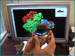
11) Flying. The Oculus Rift detects head turns but has no way to detect linear motions. Moving through a scene requires another input device. We used a Space Navigator six degree of freedom input device (hockey puck) from 3dconnexion to move around and rotate. Pushing on the device knob moves the camera through the scene. For molecular visualization usually devices move the objects rather than the observer, so this flying mode required some software modification. Pushing the knob forward moves you in the direction you are viewing, even if your head is turned. This felt natural even though it is not the direction your feet would move you forward. The device also allows rotation which duplicates the change of view achievable by turning your head. This is useful when using the oculus seated, to change view point to look 180 degrees behind you without spinning around in your chair.