
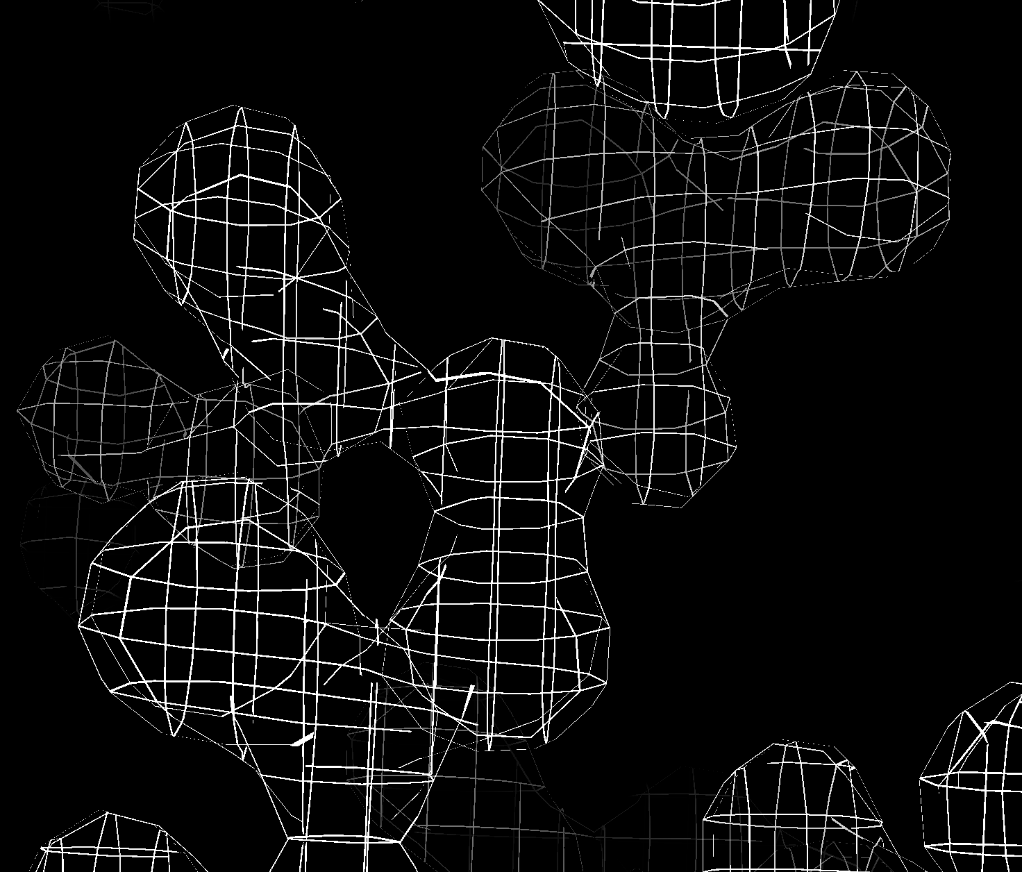
Grating along x,y,z.

Grating with constant width normal vector correction.
Grating with lines omitted where surface is within 45 degrees of parallel to grating plane.
Tom Goddard August 13, 2020
Modern OpenGL core profiles don't offer line widths except for 1 pixel. On retina or high-dots-per-inch 4K displays these lines are very thin and faint and two pixel width lines would be better. Here I looked at a few ideas to provide mesh lines greater than 1 pixel wide. I found nothing usable. The use case I was thinking about is building atomic models in large cryoEM or X-ray maps where mesh display of the density map is common. ChimeraX ticket 1315 discusses the problem.
The bottom line is that OpenGL abandoned lines thicker than one pixel, and given the advent of high-dpi displays that makes line drawing less useful with only 1 pixel lines. Getting good speed and appearance is very complex. ChimeraX may migrate from OpenGL to Vulkan some day. The Vulkan spec allows linewidths > 1 although I do not know if the drivers support it.
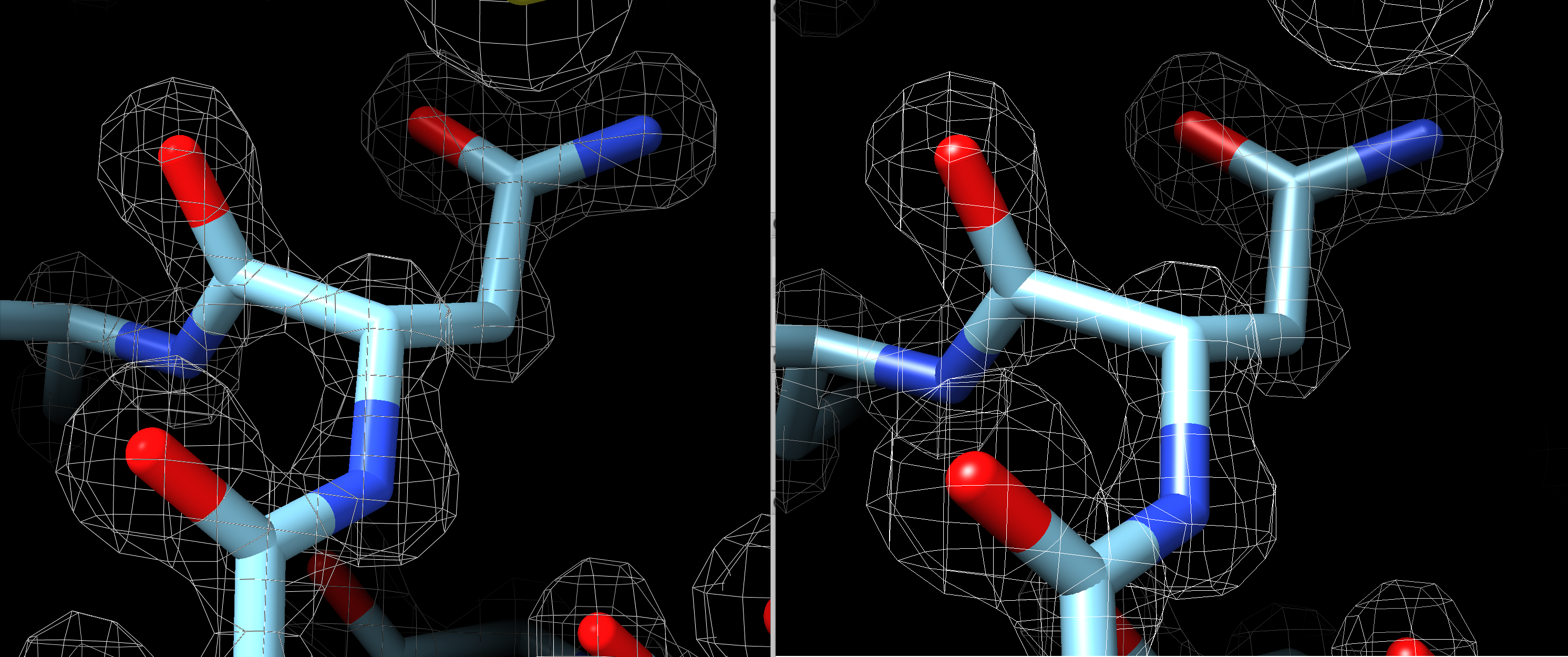
Here is 1 pixel width lines in ChimeraX compared to 2 pixel width lines in Chimera 1.14 (using legacy OpenGL).
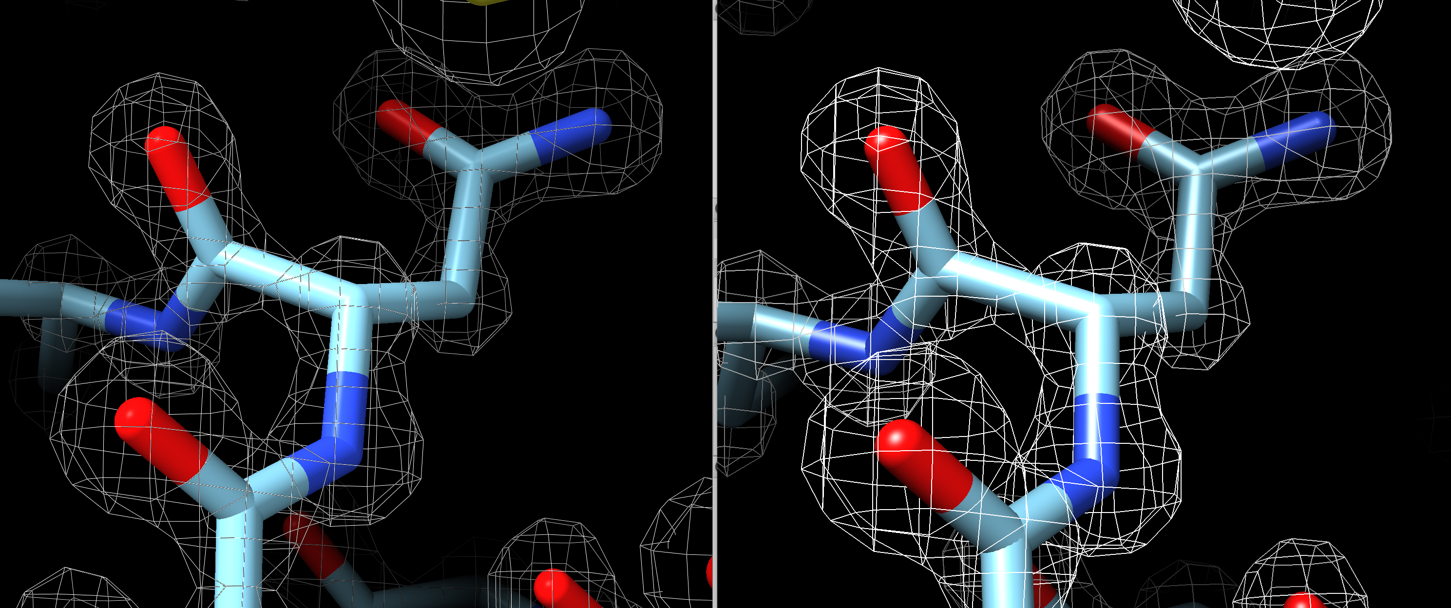
By default Chimera 1.14 shows 1 pixel width line volume meshes that look very similar to ChimeraX as shown here (ChimeraX 1.1 left, Chimera 1.14 right).
First I tried a method that would only work for volumes that shows the volume surface and slices it through a grating along the 3 axes. In other words keep pixels with mod(x,spacing) <= thickness or mod(y,spacing) <= thickness or mod(z,spacing) <= thickness. It is very simple, just a couple extra lines in the fragment shader. But it is pretty ugly. The ribbons of surface are sometimes very wide where the surface is nearly parallel the grating plane. I'll attach an image of that. I then tried to make the ribbon width more uniform by using the surface normal vector. That improved appearance a bit but didn't work as well as expected because the surface normal I need is the triangle normal but current code only has the interpolated vertex normal. I then tried not showing the ribbons where the surface makes less than a 45 degree angle with the normal. That is not horrible, but the ribbon lines just end in places and it looks a bit tattered. With all these tests I used mesh lighting off because mesh lighting on looked worse. My conclusion was that while the grating method is simple, it is just uglier in appearance. I was excited to try it because it would allow closer mesh spacing than the volume grid spacing which could be nice. It also makes the mesh lines an (approximately) fixed width in Angstroms not pixels. It was interesting but a failure.
|
Grating along x,y,z. |
Grating with constant width normal vector correction. |
Grating with lines omitted where surface is within 45 degrees of parallel to grating plane. |
I looked at two other method that I did not try. The standard technique is to use a geometry shader that turns each line segment into two triangles facing the camera. It can work and look good. The joins of two segments can look bad for thick lines since a simple approach will make each segment have square ends. But for the common 2 pixel wide line that probably will look fine. The basic geometry shader is simple enough, maybe 20 lines of code. But the geometry shader sits between the vertex and fragment shaders so it would have to know about all the different variables that pass between vertex and fragment shaders (lighting normals, textures, clip planes...) and those variables differ based on what graphics features are being used. So its a real nightmare to pass all that stuff through. This looks like just too much complexity for too little gain.
A third method I considered but did not try is simply to render the mesh multiple times offset by a half pixel in maybe 6 directions to thicken up the lines. It would probably work but would be 6 times slower and that only gets thickness 2. To go to thickness 4 would take about 24 times slower. Probably fine for saving an image, but I am more interested getting thicker lines for interactive x-ray and cryo-EM model building where the meshes can be huge. So really slow methods don't look too attractive.
Another slow method might simply be to make the mesh lines box beams each with 8 triangles for use with no lighting so the edges are not too distracting. 8 times slower and joining the segments nicely might be painful. Computing the mesh triangles would slow changing contour level. Lots of sacrifices in performance for too little gain.
Here is fragment shader code I used for testing the grating method. There was also a few lines in the vertex shader to pass scene vertex and normal vscene, nscene.
 float spacing = 0.37, thickness = 0.01;

/*
 if (mod(vscene.x, spacing) > thickness &&
     mod(vscene.y, spacing) > thickness &&
     mod(vscene.z, spacing) > thickness)
  discard;
*/

 /*
 if (mod(vscene.x, spacing) > thickness*sqrt(1-nscene.x*nscene.x) &&
     mod(vscene.y, spacing) > thickness*sqrt(1-nscene.y*nscene.y) &&
     mod(vscene.z, spacing) > thickness*sqrt(1-nscene.z*nscene.z))
   discard;
 */

 if ((abs(nscene.x) > 0.707 || mod(vscene.x, spacing) > thickness) &&
     (abs(nscene.y) > 0.707 || mod(vscene.y, spacing) > thickness) &&
     (abs(nscene.z) > 0.707 || mod(vscene.z, spacing) > thickness))
  discard;